Single Phase Soft Starter Circuit Diagram
This video will EXPLAIN how a three wire motor starter circuit works, show wiring diagrams of the circuit in each stage of the process and show examples of t.
Wiring 3 Phase Motor Starter Boost Wiring
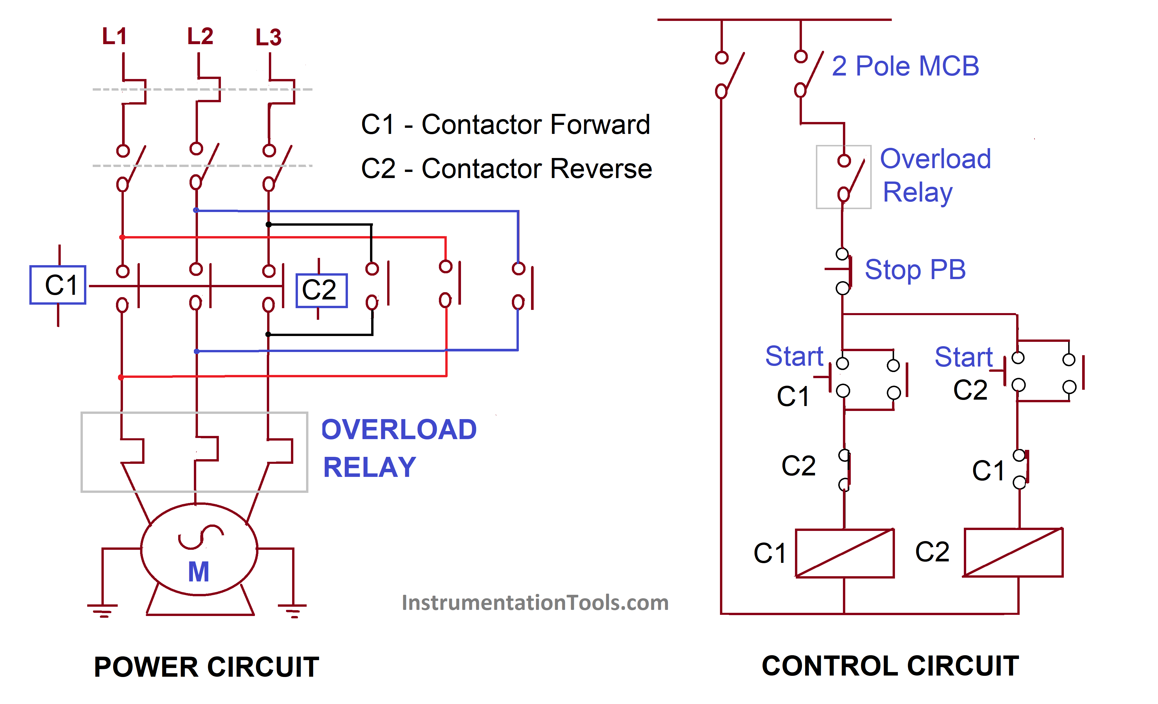
In the diagram of Power Circuit of Star Delta Starter, U2 and V2 of 3 phase motor should be connect to 4 and 6 respectively instead of U2 and V2 are connected to 6 and 4 of Delta Contector KM2. There is minor correction is require to change (printed in boxes) sequence of 3 phase wires from W2 V2 U2 to W2 U2 V2 to get Delta connection properly.

Start Stop 3 Phase Motor Starter Wiring Electrical Engineering Updates
The starter circuit All the components are earthed to the metal car body. Only one wire is needed to carry current to each component. The starter switch is usually worked by the ignition key. Turn the key beyond the 'ignition on' position to feed current to the solenoid.
Starter motor, starting system how it works, problems, testing
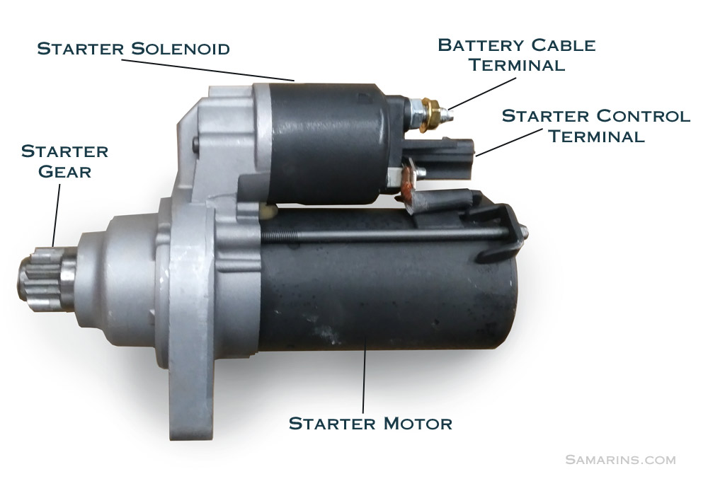
Starting system simplified diagram. As we mentioned, the starter motor requires very high electric current to turn over the engine. That's why it's connected to the battery with thick cables (see the diagram).
Autotransformer Starter Working & Diagram ElectricalWorkbook
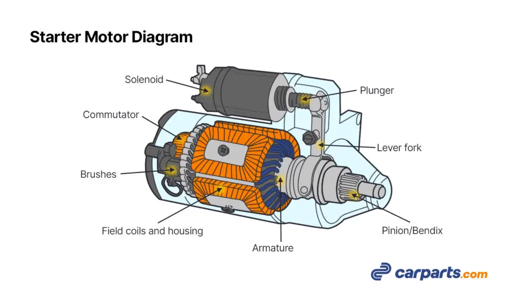
This video explains the working of a starter motor with relevant animations. The starter motor model shown here is a pre-engaged type starter motor. In this.

46+ 3 Phase Motor Starter Wiring Diagram Pdf Missouri
1- Motor Starter: Motor starter is an electrical device. It is used for motor start and stop safely. It is also used for motor protectionas overload, short circuit and phase prevention. It can be categorized in basically two types controlling like as electrical and digital.
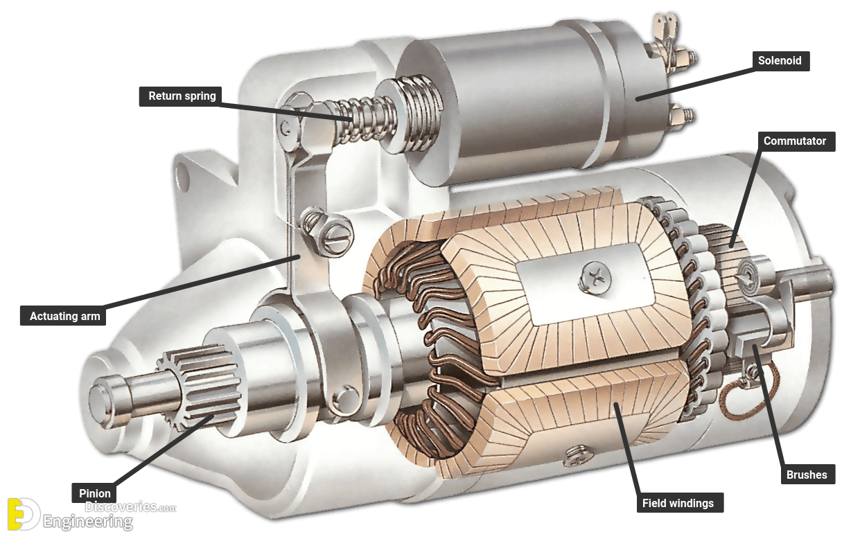
Starter Motor Parts and Functions 7 Important Parts All Car Fix
A starter motor diagram is a visual representation of a car's starter motor assembly, outlining various parts of starting system including the starter wiring, and starter control circuit. It is a useful tool for understanding how the starter motor works, identifying issues, and carrying out repairs. Parts of a Starter Motor
Electric Motor Starter Wiring Diagram
A starter motor or starting motor, or cranking motor, is a direct current motor that cranks the engine for starting. Cranking the engine means rotating the crankshaft by applying torque on it so that the piston may get reciprocating motion. The starting motor is mounted on the engine flywheel housing.
Motor Starter Wiring Diagram Pdf Download Wiring Diagram Sample
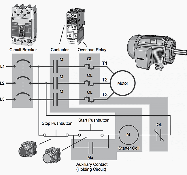
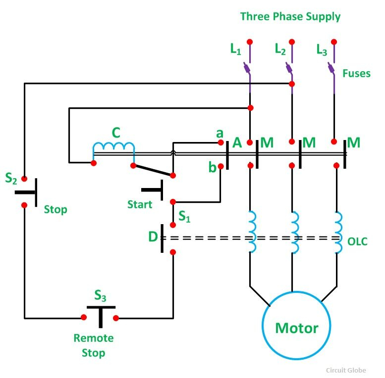
The three-phase electromagnetic motor-starter consists of a power contactor and an overload relay, as shown in Figure 2. The mechanical closing of the power contacts is accomplished by an electromagnetic field, which is produced by a coil of wire contained in the solenoid.
Dol Starter Wiring Diagram For Single Phase Motor 4K Wallpapers Review
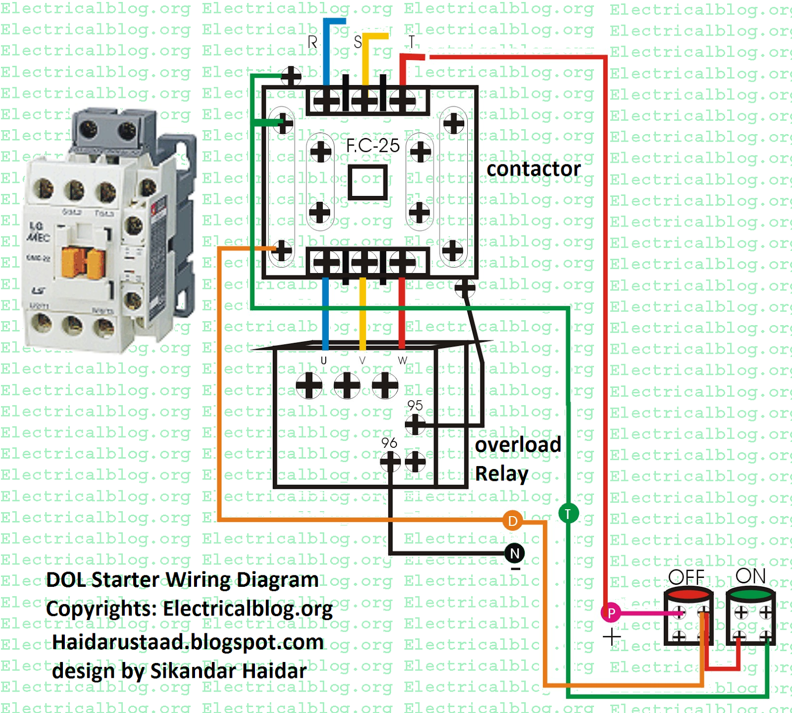
By Leela Prasad. The primary function of a motor starter is to start and stop the motor to which it is connected. These are specially designed electromechanical switches similar to relays. The main difference between a relay and a starter is that a starter contains overload protection for the motor. So the purpose of the starter is twofold, i.e.

Motor Starter Wiring Diagram
Diagrams ww introduction This booklet has been prepared as a guide to some of the useful ways Allen-Bradley's manual and magnetic across-the-line starters may be applied. It will also serve as a useful aid where simple wiring systems are to be studied. When applying these diagrams, it is well to remember that the features described in

Motor Starters
Cost Of A Starter Motor Up To 50% Cheaper Than Franchise Dealers. Get A Price Now. Low Cost Part Replacements in UK. Get A Fair Price In Seconds - Book Online Today!

Starter Motor Wiring Diagram
Upto 60% Off Car Parts at GSF - Browse Our Extensive Range Now! Easy Part Finding With Our Car Registration Look Up Tool! Huge Discounts on Quality Parts.
Starter Circuit Wiring Diagram Styleced
Siemens Motor Starter Wiring Diagram (A Complete Guide) by Charles Clark November 7, 2023. Siemens motor starters are essential for controlling the operation of electric motors. They ensure that motors start, stop, and run smoothly, protecting both the equipment and the personnel involved. Understanding how to wire them is crucial for various.
Parts And How To Work Self Start Mechanism Engineering Discoveries
DC Motor Starters and Their Circuit Diagram This article covers various types of starters for the DC motors including: Manual Starters Automatic Starters Definite Time Starters Counter EMF Starter Current-Limit Starter Each type of starter along with its circuit diagram is described in detail in this section. Manual Starters

Square D Size 1 Motor Starter Wiring Diagram Florence Wiring
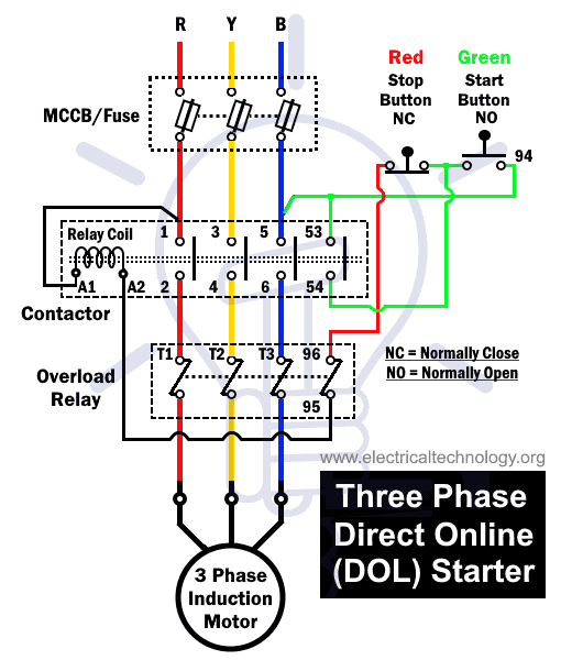
Figure 1 Contactor circuit Diagram for DOL starting Circuit operation 1. Pressing the start button completes a circuit from L3 through the normally closed stop button to coil K1/4 and the overload to L2. 2. Main contactor coil K1/4 then closes and applies full line voltage directly to the motor via contactor contacts K1.1, K1.2 and K1.3. 3.